Introduction
Designing tie-in spools / jumpers requires a large amount of analyses to be performed, i.e. various configurations, multiple load cases due to metrology and fabrication tolerances and for several subsequent load steps (e.g. tie-ins, pressure test and operation). Using software to automatically do most of the work will significantly reduce both the design time and the risk of making mistakes.
General
Development of this spool / jumper design program has been performed using the license free Python software packages. The program consists of the following features:
-
The whole field consisting of multiple spools can be set up and assessed based on a single input file;
-
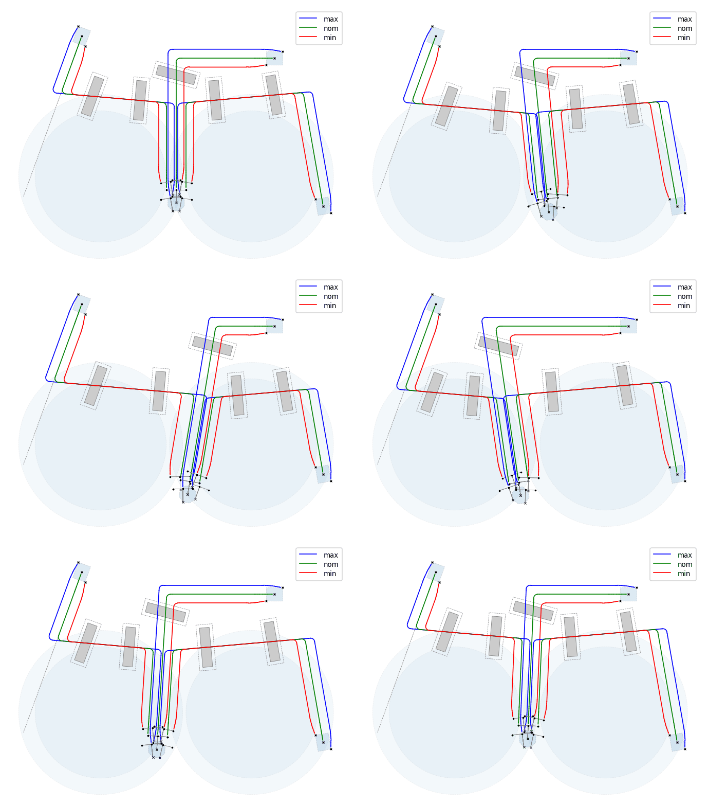
Automatic generation of critical and nominal spool configurations (e.g. min, max and nom). Geometries which are calculated based on installation tolerances and nominal coordinates / headings of the connecting structures. Installation tolerances are defined as either target boxes or target circles. Animation below shows an example of spool configurations (top-view) adapting to translation and rotation of a common structure;
Layout Animation (min/nom/max Confgurations)

-
Supports can easily be defined relative to any of the spool configurations;
-
Easy setup of various spool configurations, enabling both horizontal and vertical connection systems to be assessed;
-
Option for automatic calculation of bend angles based on spool geometry, nominal gap, support heights and hub heights;
-
Option to include connecting structures in the model, which can reduce conservatism and increase accuracy of the results;
-
Weld types can be defined with various SN-curves and SCFs, for fatigue assessment, and / or SCF and SIF for ASME and HISC code checks;
-
Material options are carbon steel (with or without internal clad), or duplex stainless steel. Coating and corrosion options are available;
-
Automatic selection of critical load cases based on selected metrology and fabrication. With option to reduce conservatism by using coupled metrology and fabrication tolerances, e.g. pitch and heading tolerances can be coupled (i.e. not treated independently).
Loads
The following load options are included:
-
Gravity;
-
Internal and external pressure;
-
Content mass;
-
Surrounding medium density (seawater);
-
Buoyancy;
-
Temperature;
-
Added mass (for modal assessment);
-
Current induced loads with directions;
-
Orthotropic friction (axial and lateral) with seabed and / or supports;
-
Settlements of structures and / or supports (vertical);
-
Tie-ins displacement and rotational loads, with optional connector swivel feature;
Solving
Built in robust FE-solver, including:
-
Subsequent static analyses of load steps, i.e. where the history of previous load steps are considered;
-
Modal analysis based on contact situation from previous static load step;
Quick assessment options with the potential to decreasing design process time significantly.
Post Processing
The following design checks are integrated in the software:
-
Local Buckling - Combined Loading Criteria (load controlled condition) & Allowable Stress Design, as per DNV-OS-F101, "Submarine Pipeline Systems", August 2012. Clad JIP is used in addition for pipes with internal clad, Ref. "JIP Lined and Clad Pipelines, Phase 3, Guideline for Design and Construction of Lined and Clad Pipelines", Revision 01;
-
ASME, B31.8-2010, "Gas Transmission and Distribution Piping Systems";
-
HISC linear criteria, as per DNV-RP-112, "Design of Duplex Stainless Steel Subsea Equipment Exposed to Cathodic Protection", Oktober 2008;
-
VIV fatigue in welds is performed based on DNV-RP-F105, based on omni-directional current. Fatigue damage in each defined weld will then be calculated based on pipe geometry and SCF in each weld. Current induced VIV only available.
Plots
Automatic generation of plots, including:
-
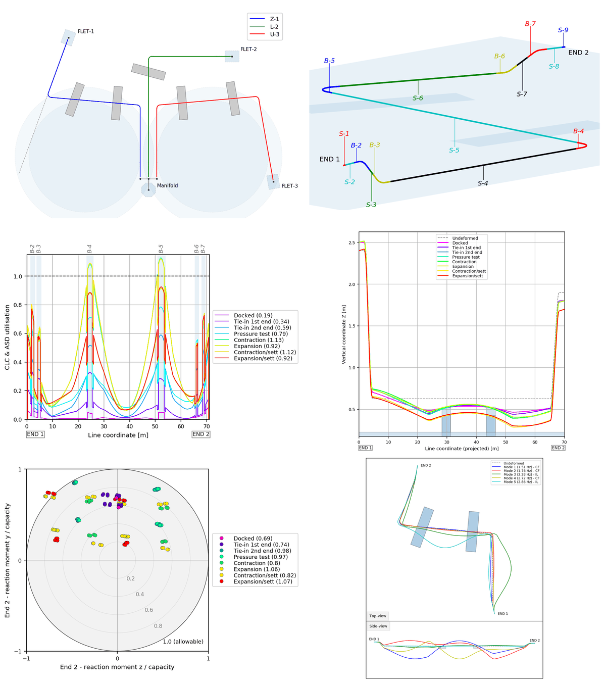
Layout plot showing all nominal spool configurations, with option to include supports, pipelines and dropped object zones;
-
Layout plot showing minimum, nominal and maximum configurations for each spool;
-
Various ISO- and top-view spool geometry plots for each spool;
-
Element result plots for each load case, including:
-
Effective and true axial force (effective section force x / section force x);
-
Lateral and vertical section forces (section force y / z);
-
Torsional section moment (section moment x);
-
Section moments about lateral and vertical axes (section moment y / z).
-
Nodal result plots for each load case, including:
-
Profile view of deformed shape for each load step along the spools, including potential contact with supports and seabed;
-
Top-view of deformed shapes for each load step.
-
Mode shape plots (side-view, top-view) for each load case, showing inline and cross-flow modes, for each matching natural frequency;
-
Sensitivity bar plots for all end reaction loads, for all load steps;
-
Utilisation envelope plots from all assessed load cases, based on the following design codes:
-
DNV's Combined Loading Criteria (load controlled condition) & Allowable Stress Design;
-
ASME allowable stress;
-
DNV's linear HISC criteria.
-
End reaction utilisation plot (for all load cases and load steps).
An extract of some generated plots are shown in slideshow below.
Miscellaneous Plots (Slideshow)

